Matrix buttons each column represent tracks, and each row represent track. Before recording your sound, first you select your clip in matrix, than open the monotone function, which is the first green button from the top right. Then in play mode, while holding the selected clip you create your sound by using the keyboard(piano keys), which will be recorded in the clip. If you add more you continue this way. It can be recorded up to eight clip. If you want to delete the sound in the selected clip, you double tap the clear.
The top four green button represent respectively monotone, play/stop, tempo and mute modes. You can arrange the tempo of the recorded sound with the tempo mode. If you want the mute the sound you press mute button. Knobs are to change the sound features like oscillator, aptitude, the length of the clip etc. You can even change the sound features while recording.


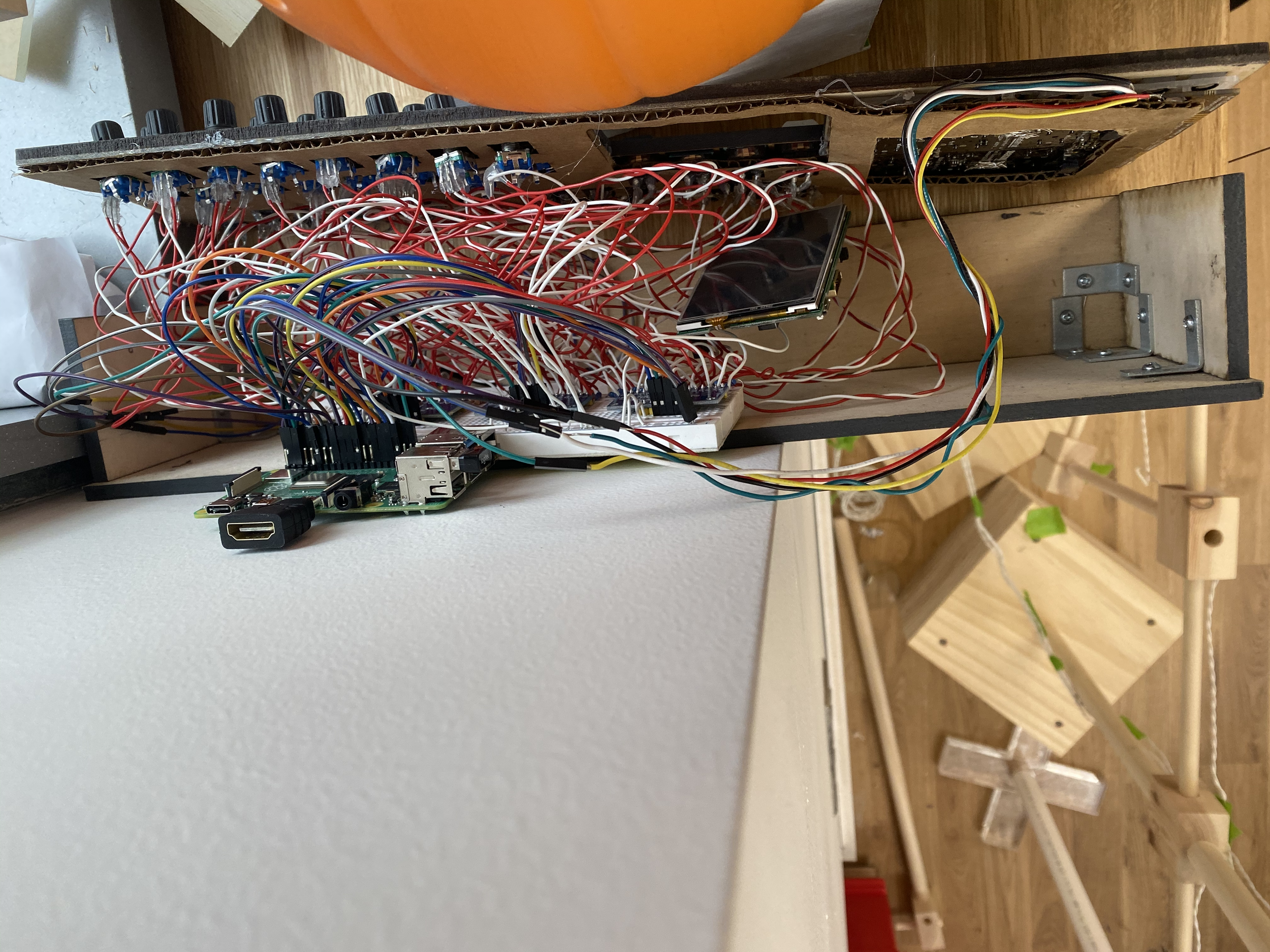
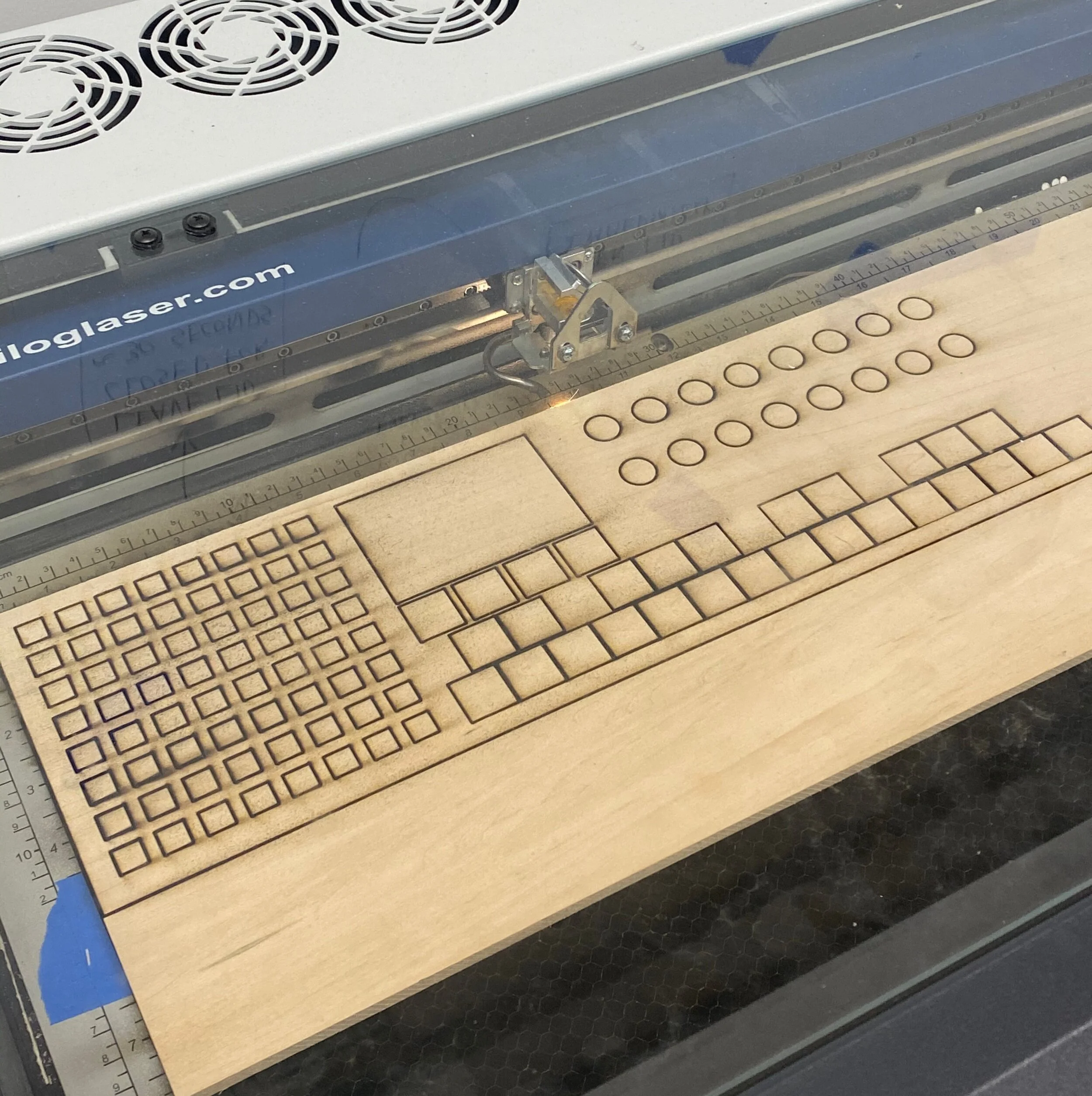
For the fabrication part of the project. We have used Raspberry Pi,4 multiplexers 16channelx1 for 29 keyboard buttons and 16 rotary encoders. We used 4 pins of raspberry for Matrix buttons, 5 pins for for each mux.(Z, s0,s1,s2,s4). Totally used, 20 pins for buttons and knobs. Vin and ground connected to breadboard. 3,5 inch display 2 pins and htmi.
Each buttons ground legs were connected to mux selectors and at the same time connected to ground with 10k ohm resistors.The positive legs fed by breadboard’s positive row. Rotary encoder have 3 legs. We have connected each A-B channel of the rotary encoders to the mux’s inputs side by side and the opposite side used 1k own resistor to the positive row. And connected the negative leg to the ground.